Sabtu, 26 Desember 2009

Implementing Open, Interoperable Building Control System

In the early days of building automation systems, before the advent of control networks, control systems consisted of pneumatic controls or wire bundles connected to relays, switches, potentiometers, and actuators. Cabling was installed in a point-to-point fashion between electrical panels, the sensor inputs and actuator outputs. The functionality of these control systems was relatively rudimentary and inflexible, and adds, moves, and changes required extensive rerouting of wiring and connections. 
The advent of solid state technology offered a means of using logic circuits to replace wire and relays. Pneumatic controls and electrical panels gave way to direct digital controllers (DDCs), which were programmed or configured not with a screw driver but a data terminal. As increasingly powerful algorithms were developed, tighter control over processes could be achieved. However, the issues associated with adds, moves, and changes remained and grew increasingly complex as systems grew in size. The software required to handle large systems was very complex, each controller represented a single point of failure, and each controller was still tethered to all of the sensors and actuators by cable bundles that were not easily modified (figure 1). Moreover, the manufacturers of DDCs developed them using proprietary internal architectures: if you wanted to expand a DDC system then you had to use components from the original manufacturer (figure 2).
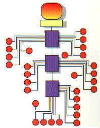


Figure 1
 Closed, wiring-intensive architecture of centralized controllers


The incompatibilities between products from different manufacturers were highlighted when customers attempted to interconnect DDC systems or devices from different manufacturers. The use of incompatible communication protocols, data formats, and electrical interconnections made it very difficult to exchange information. Seeking the communication equivalent of the "least common denominator," systems integrators and manufacturers turned to the use of gateways at the workstation level to tie together subsystems from different manufacturers.

                                                       LAN Connection Between Workstations


Subsystem 1                             Subsystem 2                             Subsystem 3
Figure 2
Using Gateways In Workstations To Link Subsystems
From Different Manufacturers

  
The problem was that these gateways didn't provide a detailed, seamless view into the different systems to which they were connected. They allowed only limited status and control information to be passed between the different systems. Fault status information couldn't be shared, information from different sensors wasn't accessible for combinatorial logic programs, and systems couldn't adapt their responses in real-time based on receiving the overall system status. In addition, the gateways needed to be changed whenever one of the subsystems was modified, creating an open-ended development and support problem for integrators and facility owners alike.

Interoperability and Open Systems
Creating a seamlessly integrated control system requires interoperability among the components of that system, as well as other related systems that must exchange information (figure 3). Interoperability is the process by which products from different manufacturers, including those in different industries, exchange information without the use of gateways, protocol converters, or other ancillary devices. Achieving interoperability requires a standardized means of communicating between the different devices and managing device commissioning and maintenance; it depends on a system level approach that includes a common communication protocol, communication transceivers of different types, media routing, object models, and management and troubleshooting tools.
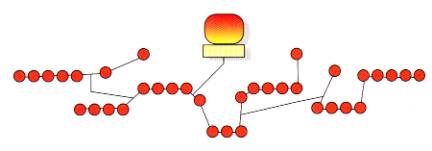
 
Figure 3
Open, interoperable control network with minimal wiring


The benefits made possible by interoperability are many. Since one sensor or control device can be shared among many different systems, fewer sensors/controls are needed and the overall cost of the control system drops appreciably. For example, in a building automation system one interoperable motion sensor can share its status with the zone heating system for occupancy sensing, the access control system for request-to-exit purposes, the security system for intrusion detection, and the fire alarm system for occupancy sensing. The motion sensor still performs the same task - detecting motion - but it can share the information with the many subsystems that can make use of its status.
The ability to share more information between systems makes possible many long sought-after applications, including integrated energy control systems. For example, in response to access control reader data and daylight illumination sensors, the HVAC and lighting systems can automatically adjust the comfort and illumination levels in pertinent work areas based on individual preferences and energy costs. Lighting can be adjusted on a cubicle-by-cubicle basis for computer operators and occupants near windows - either automatically or through commands entered from a user's PC via the corporate LAN. Heating and air conditioning can be similarly tailored. Or, based on signals from smoke detectors, the HVAC system can create positive or negative air pressure of select areas to cause a fire to move away from occupied areas while the lighting system leads the way to the closest exit. The possibilities are limited only by the creativity of the designers.
For a facility owner, interoperable products offer the advantage that devices can be selected from among different manufacturers; the owner is no longer tied to any one manufacturer's closed technology. Aside from the cost savings achieved by open competition, the facility owner is safe in the knowledge that replacement products will be available if any one manufacturer goes out of business or discontinues products. Service contracts can be openly bid since no proprietary devices will be used, thereby avoiding single source service contracts.
Interoperability also benefits equipment manufacturers because their products will be assessed based on their quality and functionality - not on their ability to meet a closed, proprietary specification. Interoperability levels the playing field and increases competition, insuring that the best devices for the job will win.

The Dawn of BACnet
In an effort to create a standardized method of interconnecting heating, ventilation, and air conditioning (HVAC) subsystems from different manufacturers, the American Society of Heating Refrigeration and Air Conditioning Engineers (ASHRAE) set about to create an open standard called Building Automation and Control NETwork (BACnet). BACnet was originally intended to eliminate the need for proprietary gateways between workstations by defining a standardized means of communicating over a local area network (LAN) to which the workstations were connected. Several different LANs were defined including point-to-point, master slave/token passing, ANSI/ATA 878.1, ethernet, and LonTalk® (an open control standard also known as ANSI/EIA 709.1).
BACnet defines a messaging format that uses objects (a logical representation of an input, output, or functional grouping of inputs and/or outputs), properties (the characteristics of an object through which it is monitored and controlled), and services (the means by which BACnet devices obtain information from one another). Since under BACnet, devices can have varying levels of functionality, even if they perform the same task from an end user's perspective, BACnet defines conformance classes that categorize the capabilities and functionality of devices.
Devices within a conformance class must have a minimum set of features, but optional features are permissible. All of the features of a device are presented in a device's Protocol Implementation Conformance Statement (PICS). A specifying engineer needs to know which objects and services are supported by which devices, since this varies from device to device, and the PICS provides most of this information. The PICS represents a point at which manufacturers can diverge in their implementation of BACnet - products which appear to perform identically may vary considerably in terms of their functionality and the accessibility of data.
While the BACnet standard had the potential to be open and non-proprietary, the means by which it has been implemented varies considerably from manufacturer to manufacturer. This variability has undermined the fundamental precepts of what BACnet was intended to be and do, and has resulted in the creation of closed, proprietary BACnet devices. Proponents of BACnet envisioned, and facility owners have the right to expect, that BACnet workstations, sensors and actuators from different manufacturers may be used seamlessly in a common control network, and that devices from one manufacturer can be replaced by devices from another manufacturer without assistance from the manufacturer or the redesign of the control system. Due to variations in the implementation of BACnet PICS by different manufacturers, however, neither scenario has been realized. In short, BACnet devices from different manufacturers are neither interoperable nor interchangeable.
In an effort to bridge the gap between existing control networks and BACnet networks, and to appease engineers who are specifying BACnet because of its promise, some manufacturers have turned to BACnet gateways. The function of a BACnet gateway is to convert data from the format used by one control network into the BACnet format. This allows the manufacturer to state that a product supports BACnet because BACnet packets can be received by the gateway and forwarded to the non-BACnet system, and vice versa.
The problem is that the use of a gateway violates the spirit of BACnet and fails to deliver interoperability to control systems. Why? As discussed earlier, in the process of converting information between two networks a gateway discards information, thereby limiting the scope of the tasks that can be performed across the gateway. Diagnostic information from nodes, network traffic statistics, network management messages - all are affected by the insertion of a gateway. While gateway manufacturers may have had the best of intentions in mind, gateways do little to realize the promise offered by BACnet and instead merely extend the life of closed, proprietary systems.
The vision of a unified BACnet network has been lost, transformed into the reality of islands of proprietary networks linked by workstations and gateways running the BACnet protocol over IP-based LANs. Like silicon curtains, BACnet workstations and gateways impede the free flow of network information, making impossible peer-to-peer communication between sensors and actuators situated within different proprietary islands.
Furthermore, the market demand has moved beyond just integrated HVAC systems to integrated systems encompassing HVAC, lighting, security, life/safety, power management, submetering, and other control systems. These other applications were not contemplated for BACnet, and the protocol was not optimized for their operation.
This begs the question of what a specifying engineer or facility owner has the right to expect from an open, interoperable control system. If one accepts the original intentions of BACnet then one has the right to expect lower installed costs (due to open competition among vendors for like, interchangeable products), lower life cycle costs (from service contracts and/or replacement parts that can be purchased from multiple suppliers under an open bidding process), and enhanced functionality and expandability (from the many building control systems that can be interconnected with HVAC systems). To date BACnet has not delivered on its promise, and while beyond reproach in concept, BACnet has been sullied by hype that hasn't been matched in the execution of BACnet compliant products or systems.

LONWORKS® Technology
One of the control networks specified within BACnet for communications between sensors and actuators is LONWORKS. Developed by Echelon Corporation, Palo Alto, California, LONWORKS technology allows all manner of control devices to communicate with one another through a common communication protocol that is shared among all devices. Communication transceivers and transport mechanisms are standardized, as are object models and programming/troubleshooting tools to enable the rapid design and implementation of interoperable, LONWORKS-based devices. Network management software, protocol analyzers, Internet Protocol (IP) servers, network interface cards, and development tools are all available off-the-shelf to speed development and reduce time to market. In short, LONWORKS offers a system level approach to interoperability, and comprises a complete set of tools and products.
The heart of a LONWORKS hardware device is the Neuron® Chip, an integrated circuit that combines a sophisticated communications protocol, three microprocessors, a multitasking operating system, and a flexible input/output scheme. Manufactured under license by Cypress, Motorola, and Toshiba, the Neuron Chip is sold and supported worldwide. Almost 10,000,000 have been shipped since 1992. Devices that complement and/or use Neuron Chips are available from Echelon and roughly 4,000 manufacturers worldwide.
Ensuring the interoperability of these network communications is the responsibility of an organization called the LONMARK® Interoperability Association. Funded through member dues, the LONMARK Association defines the interoperability guidelines for LONWORKS devices, including communication transceivers and object models. Products that bear the LONMARK logo are certified to adhere to the LONMARK interoperability guidelines and can be used with confidence in integrated control systems.
LONWORKS has been successfully used in a wide range of industries - building and industrial automation, transportation, and home/utility automation are the four largest markets for LONWORKS products. Besides its inclusion in BACnet, LONWORKS has been included in many international standards including IEEE 1473 (train control), ANSI/EIA 709.1 (control networks), TC247 (building automation), AAR (electro-pneumatic train braking), and the SEMI standard (semiconductor manufacturing equipment). Its inclusion in so many international standards has validated LONWORKS as an open standard. Likewise, its use by thousands of manufacturers, across many industries, has proven the utility of LONWORKS for a wide range of applications.
One of the reasons behind the success of LONWORKS is the availability of a powerful network management architecture that can accommodate real-world installation scenarios. After all, even a well designed control system needs to be changed from time to time. The LONWORKS Network Services operating system, LNS, provides a powerful client-server architecture that permits multiple installers to simultaneously configure a control system. In order to speed commissioning of devices from different manufacturers, LNS defines a "plug-in" standard. This standard allows sensor, actuator, and device manufacturers to provide customized applications for their products. When those products need to be configured, an LNS-based tool will automatically present a configuration screen that the manufacturer has tailored to the device being configured. Regardless of the LNS-based tool being used, the configuration screen for that product will remain consistent. This capability simplifies the task of training installers, allows device manufacturers to give the programming interface a unique look and feel, and permits tool vendors to offer products that are both unique looking and interoperable.
Figure 4 shows the LonMaker™ for Windows® Integration Tool from Echelon, an LNS-based tool that implements a Visio® user interface. Visio provides users with a familiar, CAD environment in which to design a control system, and Visio's smart shape drawing environment offers an intuitive, simple means for creating devices. The tool includes a number of smart shapes for LONWORKS networks, and users can create new shapes for unique device configurations or complete subsystems. Stencils can be constructed with predefined devices, function blocks, and connections between them. Master shapes corresponding to complete subsystems can be created and saved. Additional subsystems can then be created by simply dragging the shape to a new page of the drawing, a time-saving feature when designing complex systems.


Figure 4
Typical LNS-Based Tool - Network Configuration Screen

 
To ensure interoperability, LNS supports the LONMARK interoperability guidelines. LONMARK features such as standard functional profiles, configuration properties, resource files, and network variable aliases make it possible to achieve interoperability between tools, devices, and tools and devices.

The Internet: Connecting Devices, Workstations and Browsers, Locally and Across the Globe
One of the underlying tenets of LONWORKS is that every device in a network should have the ability to send packets to, and receive packets from, any other device in the network without an intermediate gateway that filters and modifies information. This capability is one of the cornerstones of any open, interoperable, peer-to-peer network. Importantly for the BACnet world, LONWORKS allows customers to use an IP-based network (including LANs, WANS, and the Internet) as a seamless pathway to communicate with workstations, sensors, actuators, and displays. Where BACnet workstations and gateways act like silicon curtains and filter out information, LONWORKS Internet Servers intelligently route LonTalk packets through the IP network by tunneling, making these packets available to any sensor, actuator, or workstation that needs them.
For example, Echelon's i.LON™ 1000 Internet Server (figure 5) incorporates Cisco's Network Foundation Technologies to offer Layer 3 packet routing through an IP network. Certified by Cisco under their NetWorks™ program, the i.LON 1000 seamlessly links the data and control networks, allowing the IP network to be treated as an extension of the LONWORKS network, and vice versa. All of the features of LONWORKS networks - peer-to-peer networking, network management, device diagnostics, software downloading, secure access, and so on - are supported over IP networks. From the IS perspective, the i.LON 1000 includes SNMP MIB II, TCP/IP, UDP, DHCP, ICMP, SNTP, TOS, HTTP, FTP, and MD5 support. The i.LON 1000 also includes a programmable packet aggregation feature which throttles the rate at which control packets are broadcast on the IP network, ensuring that the IP network is not overwhelmed with control-related packets.
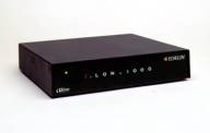
 
Figure 5
i.LON 1000 Internet Server


The ability of the i.LON 1000 to tunnel LonTalk packets through an IP network allows devices to communicate on a peer-to-peer basis across a LAN that connects floors of a building, a WAN that connects buildings within a city, or over the Internet to facilities spread around the world (figure 6). The i.LON 1000 eliminates the need to install a separate and dedicated data network for the control system, and instead permits the existing data infrastructure to be used for control networking, saving both installation and on-going maintenance costs. The i.LON 1000's integrated Web server and access security also permits authorized support and service personnel to observe and control the LONWORKS network, using Internet Explorer or Netscape Navigator, from any PC or laptop running locally or over the Internet.
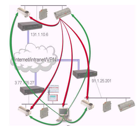


Figure 6
Peer-to-peer networking using the i.LON 1000
 
 As another example of LONWORKS IP connectivity, the standard LONWORKS network operating system - LNS - includes remote Internet Protocol (IP) client support. This feature allows software applications on IP-connected workstations to interact with an LNS Server connected to the same network. These applications can monitor, control, diagnose, or reconfigure the LONWORKS network (figure 7) via the Internet or any other IP-based network.
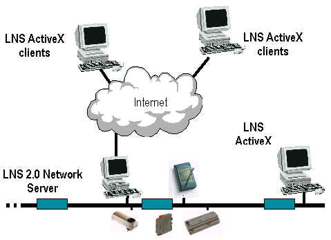


Figure 7
  Remote LNS applications run over IP networks


Used together, the i.LON 1000 and LNS provide LONWORKS networks with all of the functionality originally envisioned for BACnet devices and workstations, but without the drawbacks and limitations of the BACnet systems actually being fielded: 
  1. LonTalk and IP, both open standards in their own right, are the only protocols required for the entire network;
  2. Every device and workstation has the ability to communicate with every other device and workstation on a peer-to-peer basis;
  3. Workstation may reside anywhere on the IP network, without requiring a direct physical connection to the control devices they are monitoring;
  4. A dedicated LAN is not required;
  5. The system can be monitored and controlled over the Internet using an off-the-shelf browser and PC. No special hardware or custom software is required;
  6. The control network is gateway-free, eliminating the need to customize a gateway in the event of adds, moves, and changes in the system - or when additional, unanticipated information must be passed through the network;
  7. Seamlessly integrated systems can incorporate HVAC, lighting, security, life/safety, power management, submetering, and other building control systems.
Supplanting BACnet
While LONWORKS is specified within BACnet at the sensor bus level, the many proven capabilities of LONWORKS networks - including those which BACnet was originally intended to offer but were never realized - begs the following question: Has LONWORKS supplanted BACnet as the solution for open, interoperable HVAC control? The answer to this question should reference the original intentions of BACnet, namely satisfying what a specifying engineer or facility owner has the right to expect from an open, interoperable control system. Let's review these points individually:
  • Ability to exchange information: LONWORKS permits products from different manufacturers, including those in different industries, to exchange information without the use of gateways, protocol converters, or other ancillary devices. This is possible because LONWORKS couples a standardized means of communicating between different devices (LonTalk protocol, openly available communication transceivers, common object models) with IP connectivity and a standardized means of managing device commissioning and maintenance (LNS);
  • Meets international standards: LONWORKS is a truly open control standard that has passed muster by accredited international standards organizations (AAR, ANSI, CEN, EIA, IEEE, and SEMI);
  • Lower installed costs: Today there are thousands of companies building products that compete on the open market. End users have multiple sources of supply of interoperable LONMARK products which can be commissioned and maintained by an array of competing service and support organizations;
  • Lower life cycle costs: since LONWORKS is an open technology with multiple sources of supply and LNS-based tools that offer interchangeable Plug-Ins for device configuration, end users can let service contracts and/or purchase replacement parts from multiple suppliers under an open bidding process;
  • Enhanced functionality and expandability: LONWORKS products are available for a wide range of applications covering all aspects of building automation including heating, ventilation, air conditioning, security, fire/life safety, access control, power quality, standby power, submetering, lead detection, gas detection, refrigeration, appliance and cooking systems, sunblinds, audio/visual control, and sound reinforcement. These different products may be integrated using an LNS-based tool to perform new and innovative functions.
In consideration of these goals, LONWORKS does indeed satisfy the needs of specifying engineers and facility owners with regard to what they should expect from an open system, while BACnet does not. Moreover, the market appears to have spoken with regard to the overwhelming commercial acceptance of LONWORKS within the building automation industry, by manufacturers, integrators, and facility owners alike. According to the BCS Partners report BCS/99 - The Building Controls Systems Market (1998-2003), manufacturers representing approximately 70% of the worldwide building control system market are building and shipping LONWORKS-based products. Market leaders in the wiring device, lighting, emergency lighting, ballast, elevator, variable frequency drive, sunblind, security, fire/life-safety, closed-circuit television, standby power, power measurement, and submetering markets are likewise building and shipping LONWORKS-based products. Based on both unit shipments and actual market penetration, one can only conclude that LONWORKS is the solution for open, interoperable building control, including HVAC applications.
If the BACnet community is to avoid the painful downward spiral of CAB and other previous control standards efforts, perhaps the best future direction is to join ranks with the LONWORKS community. By joining in the efforts of the LONMARK Interoperability Association, BACnet community members can have a say in the future direction of LONWORKS and the integration of different subsystems.
Summary
The world of control systems has come a long way technologically since the advent of DDCs. The availability of LONWORKS control network technology has opened the door to a new generation of open, interoperable control systems. LONWORKS delivers on the benefits promised by BACnet - higher reliability, greater vendor choices, and lower life-cycle costs - while BACnet itself has fallen short in these areas.

Michael R. Tennefoss is the Director of Product Marketing at Echelon. 

Sabtu, 05 Desember 2009

Robotic Simulation and Off-line Programming: From Academia to Industry

Robotic Industries Association
Robotic simulation and off-line programming (OLP) are powerful tools for saving integrators and end-users time and money when designing a work cell. The ability to analyze how a work cell will behave before investing time and money on equipment makes for a smoother transition from concept to reality. “Simulation and OLP allows integrators to study multiple scenarios of a work cell before any metal is committed. Mistakes commonly made in designing a work cell can be made in advance and studied,” says Michael Jacobs, President and Chief Executive Officer of Applied Manufacturing Technologies Inc. (AMT, Orion, Michigan).
Simulation and OLP are also powerful teaching tools for engineering students.


Systems Simulated
“KMT uses simulation to figure out which robot model to use, to verify the robot’s reach and access, and to configure the tooling and equipment around the robot,” asserts Roberta Zald, Business Development Director with KMT Robotic Solutions, Inc. (Auburn Hills, Michigan). “Simulation streamlines and accelerates the process by getting a visual and a mathematic-based conclusion of how the robotic system will look, what components will go into it, and how the work cell will be configured.”
Zald’s colleague at KMT, Simulations Manager Reggie Aquino adds, “Simulation is an engineering tool to estimate cycle time and to find bottle necks on production lines in complicated systems. Simulation is used to determine if a design concept is going to work for the flow of the product.” Aquino notes that simulation is a good sales tool. “Simulation gives customers unfamiliar with robotics a better idea of what robots can do by literally showing them the process.”


Cycle Times
“Simulation is used by Motoman Inc. and our integrators for reach studies and cycle time analysis, and to ensure that a robotic system will do the functions that an end-user needs it to do,” says Gregory Garmann, Software and Controls Technology Leader with Motoman Inc. (West Carrollton, Ohio). “In a cycle time analysis, simulation can show how many parts per hour the work cell can create before any hardware is actually ordered by getting a very good look at the application.” Garmann adds, “A work cell’s details are more accurate if integrators can do a detailed analysis on the robot’s reach and cycle times.”
Likewise, “Simulation allows integrators to look at a process, fine-tune it, and see what the cycle times will be,” contends Chad Henry, Applications Engineering Manager at Stäubli Corp. (Duncan, South Carolina) Henry points out that, “Integrators cannot account for all of the factors that contribute to overall cycle time, but a majority can be accounted for while making assumptions based on experience.”
Henry shows how simulation and OLP can save time and money when designing a robotic work cell. “By quickly teaching some points in simulation and running the virtual robot before spending much time developing the application, integrators get a good idea of cycle times. Integrators can move some devices within the work cell, reposition the robot, or use two robots to get the proper cycle time.” Similarly, “OLP and simulation help balance the work load among multiple robots within a work cell,” says Aquino.


End-users can simulate tasks the work cell will do as well as simulating the cycle time of the robot, says AMT’s Jacobs. “Cycle times can be modeled exactly using robot manufacturer's realistic robot simulation (RRS) modules so end-users can know in advance how a system will perform. Simulation has morphed into a larger concept, digital manufacturing, which in turn is a subset of a larger industrial concept of product life cycle management, (PLM), a holistic approach to managing the manufacturing processing.”
Reaching Robots
Simulation and OLP avail themselves to reach studies, says Chahe Bakmazjian, President of Jabez Technologies Inc. (St-Laurent, Quebec, Canada) “Simulation and OLP help in reach studies, where end-users are looking for graphical tools to decide where to place the part in respect to the robot. If the program has problems with reach or joint limits, end-users want tools to manage these problems.”
Using OLP and simulation ensures a robot can get in and out of tight areas to perform its tasks, says, Anthony Karew, Senior Consulting Engineer with DELMIA Corp. (Auburn Hills, Michigan) “Simulation and OLP are used to validate the part in the gripper and to make sure the robot has ingress and egress, as well sufficient reach. End-users want more enhanced tools to determine reach and help with robot placement.”


Path Generation
OLP and simulation tools help integrators create the optimal program paths for the robot. “Using mathematical data of the part to be cut or trimmed, OLP can program a much more complex path than could be done than when programming manually. For example, milling a part from a block involves thousands of points of programming and the only viable way to perform that task is using OLP”, contends Zald of KMT. “Most robot manufacturers have their own simulation packages that increase the capabilities of Computer-Aided Design (CAD)-to-path programming. CAD-to-path functionality significantly streamlines the path programming requirements for material removal applications.”
Aquino uses robotic trimming of automotive instrument panels as an example of a challenging application to simulate. “Automotive instrument panels are difficult to program off-line because they have so many tight areas that require trimming,” says Aquino. “Care needs to be taken to ensure that the end-of-arm tooling can access each area to be trimmed and the programmer must look out for interference issues off-line by using collision detection software.”
Aquino goes on to say, “The process of off-line programming with collision detection software enabled can be a time-consuming task, but can also save significant time on the actual production system. Using off-line programming tools is key to improving the efficiency of actual robotic work cells.”
Computing a robot path without collisions makes simulation and OLP particularly useful, proposes Karew of DELMIA. “End-users want automatic collision-free robot path planning and an intuitive simulation tool to calculate that path. We have implemented tools that help with robot path planning.”
Bakmazjian has a similar take on OLP-based robot path generation. “OLP can generate the robot’s path in a simulation using a virtual environment on a computer. OLP generates automatic paths using CAD-CAM (Computer-Aided Manufacturing).”
Michael Jacobs of AMT adds, “End-users use robot frames in simulations, a reference coordinate system incorporated into the program. Only a single frame might need to be adjusted rather than an entire path when the robot is put into a factory,” says Jacobs. “With more sophisticated simulation tools, the path requires fewer adjustments.”
Process-intensive applications such as welding have details not present in applications like material handling. “Details in welding applications can be more difficult to simulate,” says Garmann of Motoman. “Integrators may program the robot’s path very accurately but the other information such as welding parameters and settings have to be added to the system to do a complete OLP process.”


Sim School
Robotic OLP and simulation are not only powerful tools for integrators but for engineering educators as well. “Simulation and OLP are valuable in teaching robotics courses and as a practical tool to show engineering and technology students how to design work cells using a computer. Students, while not hurting anything or anyone through the use of OLP and simulation, learn a great deal about robotic technology,” maintains Jim Devaprasad, a professor at Lake Superior State University’s (LSSU, Sault Sainte Marie, Michigan) School of Engineering and Technology, and Director of its Robotics Center.

Devaprasad states, “Students like to see immediate results through watching a virtual robot. Students are as equally excited as using a simulated robot as when using an actual robot.” Devaprasad continues saying, “We teach students how to develop code and see the results by animating the robot. Programming and learning robotics processes in a virtual world is an effective precursor to using an actual robot.”
Like Aquino, Devaprasad uses OLP and simulation as a “sales tool.” “Using OLP and simulation in a demonstration opens prospective engineering students’ eyes and sparks interest in software and technology,” remarks Devaprasad. “Getting qualified people who understand both robotics hardware and simulation software in combination is a challenge for many engineering companies. Not many people are proficient at both, but our students are.”
Simulation and OLP helps train students in robotics work cell design and optimization, says Devaprasad. “Using a generic robotics simulation software package, I can assign students to investigate how different types and models of robots can solve an assembly problem, enabling students to converge to an optimum solution.”


Real Versus Virtual
How closely does OLP and simulation reflect reality on the shop floor? Very closely, declares Stäubli’s Chad Henry. “If integrators have a very detailed three-dimensional layout of a work cell, the program can be very representative of what the actual layout will be. While some variables cannot be accounted for if the integrator does not yet exactly know what devices the robot will be working with.”
The virtual and real worlds could match as closely as is necessary, says Karew. “If integrators do their engineering homework, the virtual work cell can be exactly like the real world work cell. Integrators simulate the work cell, download it to the robot, and touch up the program a little if necessary.”
Greg Garmann agrees. “The difference between the real world and the virtual world will become much closer as calibration tools continue to grow. With higher speed processors and higher speed capabilities in motion control, along with new motor technology, will provide a better response rate of the system.”
As simulation has become more prevalent in robotics, integrators have learned how to better match the tasks a work cell will perform with a suitable robot. “When simulating a work cell, integrators have to size the robot appropriately and make sure the payload capacity is right. I suggest that integrators quickly teach some points in simulation and let the virtual robot run a few cycles to get a good idea of cycle times,” says Chad Henry. “Running the virtual robot should be done before spending much time developing an application.”

Communication between the integrator and the end-users is important, says Henry. “Check with the end-user to make sure you can change the position of the robot, rearrange devices, and make modifications to the end-of-arm tooling.”
Michael Jacobs also believes communication between the end-user and integrator is vital to successful work cell. “When using simulation and OLP, have solid communication with the people who are designing the process and those responsible for implementation of the work cell on the factory floor. End-users need to understand the simulation is part of the entire manufacturing system.”


Ongoing OLP
Jacobs foresees OLP merged with other facets of digital production. “In the coming years, OLP will be incorporated into other digital manufacturing tools, such as virtual commissioning, which is a simulation of the control systems in a work cell. As these tools get used more, integrators will be able to incorporate all of a work cell’s control logic in the simulated work cell.”

Jacobs says simulation and OLP will become more widespread in robotics. “In the past, only large companies could benefit from simulation systems but now smaller companies can leverage OLP and simulation as they continue to be more capable and more accessible.” Jacobs adds that as robot controllers become more adaptive to their surroundings, features such as sensors, vision, touch sense and more sophisticated control algorithms will make simulation and OLP more cost-effective.
Karew sees more robotic as well as non-robotic simulation. “Processes such as human task simulation and assembly simulation will become more widespread. I see more collaboration among multiple engineers working on the same project while based in other states or other countries.”


Sabtu, 28 November 2009

Glossary of Industrial Automation

A

Terms 

Applicable Categories 

a constant read-in system

Counters 

absolute

Rotary Encoders 

absolute command

Servomotors / Servo Drivers 

absolute maximum value

Push Buttons / Indicator Lamps

absolute-value alarm

Temperature Controllers 

AC Relay

General Purpose Relays

acceleration time

Frequency Inverters 

acceleration/deceleration time

Frequency Inverters

access right

Programmable Controllers 

accuracy

Digital Panel Indicators,Signal Converters 

accuracy of operating time

Timers 

activation

General Purpose Relays 

active power

Digital Panel Indicators,Signal Converters 

adjuster setting

Photoelectric Sensors 

adjustment level

Temperature Controllers 

advanced function setting level

Temperature Controllers 

Air Cleaning Systems

Air Cleaning / Static Electricity Components 

Alarm History

Programmable Terminals 

alarm hysteresis

Temperature Controllers 

alarm latch

Temperature Controllers 

alarm operation

Temperature Controllers 

alarm with standby sequence

Temperature Controllers 

Alarm/Event Display

Programmable Terminals 

alarm/event function

Programmable Terminals 

alarm/event settings

Programmable Terminals 

Alarm/Event Summary & History

Programmable Terminals 

alarm/event summary and history functional object

Programmable Terminals 

allowable load resistance

Digital Panel Indicators,Signal Converters 

allowable switching time for mode selector input

Safety Application Controllers 

alternate

Push Buttons / Indicator Lamps 

alternate action

Push Buttons / Indicator Lamps 

alternative operation

Level Switches 

ambient illuminance

Photoelectric Sensors 

ambient operating humidity

Power Supplies 

ambient operating temperature

Power Supplies 

ambient operating temperature and humidity

Solid-state Relays 

Amplifier Unit connector

Photoelectric Sensors 

analog data allocation

Field Networks 

analog frequency

Frequency Inverters 

analog input

Temperature Controllers 

analog line


Analog Meter

Programmable Terminals 

analog reference

Frequency Inverters

analog signal

Temperature Controllers 

annunciator

Temperature Controllers 

annunciator

Digital Panel Indicators 

anode arc

General Purpose Relays 

apparent power

Digital Panel Indicators,Signal Converters 

applicable load inertia

Servomotors / Servo Drivers 

application condition

Basic Switches 

AR area

Programmable Controllers 

ASR

Frequency Inverters 

AT

Temperature Controllers 

AT calculated gain

Temperature Controllers

atmospheric pressure

Pressure Sensors 

auto zero function

Counters 

auto/manual switching

Temperature Controllers 

automatic baud rate detection

Field Networks 

Automatic Carrier Frequency Reduction Function

Frequency Inverters 

automatic energy-saving operation

Frequency Inverters

Automatic Energy-saving Operation Function

Frequency Inverters 

automatic reset

Counters 

automatic torque boost

Frequency Inverters 

Automation Systems

Code Readers,Field Networks,Programmable Controllers,Programmable Terminals,RFID Systems,Support Software,Support Software & Peripheral Devices,Wireless Components

auto-reset

Emergency Stop Switches,Enabling Components,Presence Detection Sensors,Safety Application Controllers,Safety Door Switches,Safety Limit Switches,Safety Relays,Safety Sensors

auto-tuning

Frequency Inverters 

auto-tuning

Temperature Controllers 

Auxiliary Area

Programmable Controllers 

auxiliary output

Temperature Controllers 

average processing

Temperature Controllers 

average processing function

Digital Panel Indicators 

AVR

Frequency Inverters 

Axial Fans

Axial Fans 


B

Terms 

Applicable Categories 

backlash

Servomotors / Servo Drivers 

backlight

Programmable Terminals 

backlight service life

Programmable Terminals 

Backplane-free construction

Programmable Controllers 

backup operation

Power Supplies 

bank

Temperature Controllers 

bank function

Digital Panel Indicators 

bank switch

Digital Panel Indicators 

base frequency

Frequency Inverters 

Basic I/O Unit

Programmable Controllers 

Basic Switches

Basic Switches 

basic system

Programmable Controllers 

batch counter

Counters 

batch counting function

Counters 

battery backup

Programmable Controllers

baud rate

Field Networks 

BCD

Digital Panel Indicators 

binary data

Wireless Components 

bit

Digital Panel Indicators,Signal Converters 

bit

Programmable Terminals 

Bit Lamp

Programmable Terminals 

Bit Slave

Field Networks

Bitmap

Programmable Terminals 

bits per second

Field Networks 

bits per second

Programmable Terminals 

bit-strobe connection

Field Networks 

black powder

General Purpose Relays 

blanking

Safety Sensors 

bleeder resistance

Solid-state Relays 

brake

Frequency Inverters 

Brake Control Function

Frequency Inverters

braking

Frequency Inverters 

braking resistor

Frequency Inverters 

braking torque

Frequency Inverters 

break contacts

General Purpose Relays 

brightness

Programmable Terminals 

broadcast communications

Wireless Components 

broken-line approximation

Temperature Controllers 

Broken-line Graph

Programmable Terminals 

brown powder

General Purpose Relays 

BSMI Standard

Power Supplies 

built-in amplifier

Photoelectric Sensors

built-in SSR output

Temperature Controllers 

burnout (protection)

Digital Panel Indicators,Signal Converters

Busoff

Field Networks 

Buttons

Programmable Terminals 

byte

Digital Panel Indicators,Signal Converters 


C

Terms 

Applicable Categories 

cable extension characteristic

Rotary Encoders

Cam Positioner

Counters 

Cam Positioners

Cam Positioners 

carrier frequency

Frequency Inverters 

cascade control

Temperature Controllers 

cathode arc

General Purpose Relays 

Centronics interface

Field Networks 

certification of conformance to technical standards

Wireless Components 

chameleon lighting

Push Buttons / Indicator Lamps 

chattering

General Purpose Relays 

CIO Area

Programmable Controllers 

city water

Level Switches

clearance distance

Limit Switches 

clock pulse

Programmable Controllers 

C-mode command

Programmable Controllers 

Code Readers

Code Readers 

coherency

Field Networks 

coherer effect

General Purpose Relays 

coil inductance

General Purpose Relays 

cold junction

Temperature Controllers 

cold junction compensation

Temperature Controllers 

cold junction compensation

Digital Panel Indicators 

Comm. Auto-return

Programmable Terminals 

Command Button

Programmable Terminals 

COMMAND INPUT mode

Counters 

Commercial Switching

Frequency Inverters 

common mode voltage

Digital Panel Indicators 

Communication Setting

Programmable Terminals 

communications error history monitor

Field Networks 

communications error output setting

Field Networks 

Communications Unit

Programmable Controllers 

comparative output

Pressure Sensors 

comparator

Field Networks 

comparison output pattern setting

Digital Panel Indicators 

compensating leadwire

Temperature Controllers 

complementary output

Rotary Encoders 

Complete Link Method

Programmable Controllers 

Compo Com/DaikanYama

Programmable Controllers 

CompoBus/S

Field Networks 

Componet

Field Networks

compound contact

General Purpose Relays 

CompoWay/F protocol

Temperature Controllers 

condensate

Level Switches 

conductance

Level Switches 

conductivity

Level Switches 

conduit size

Limit Switches 

connection method

Digital Panel Indicators 

Consecutive Line Drawing

Programmable Terminals 

constant torque characteristics

Frequency Inverters 

constant value control

Temperature Controllers 

contact

Limit Switches

contact capacity of output

Level Switches 

contact erosion

General Purpose Relays 

contact film

General Purpose Relays 

contact form

General Purpose Relays 

contact gap

General Purpose Relays 

contact operation monitor

Field Networks 

contact protective circuit

Emergency Stop Switches,Enabling Components,Presence Detection Sensors,Safety Application Controllers,Safety Door Switches,Safety Limit Switches,Safety Relays,Safety Sensors 

contact rating

Push Buttons / Indicator Lamps 

contact relay output

Temperature Controllers 

contact resistance

Basic Switches,Limit Switches,Push Buttons / Indicator Lamps 

contact shape

Basic Switches 

contact spring

General Purpose Relays 

contact wear

General Purpose Relays 

Contents Display

Programmable Terminals 

continuous proportion

Temperature Controllers 

Control Components

Cam Positioners,Counters,Digital Panel Indicators,Programmable Relays,Temperature Controllers,Timers 

control cycle

Temperature Controllers 

control mode

Temperature Controllers 

control mode

Frequency Inverters 

control output assignment

Temperature Controllers 

Control Output Unit

Temperature Controllers 

Controller Link

Programmable Controllers 

Controller Link Unit

Programmable Controllers 

convert

Programmable Terminals 

cooling coefficient

Temperature Controllers 

cooling fan

Frequency Inverters 

cooling method

Power Supplies 

copy function

Frequency Inverters

core

General Purpose Relays 

COS connection

Field Networks 

count value setting method

Counters 

Counter with Backlight

Counters 

Counters

Counters 

CPS

Programmable Controllers 

CPU Bus Unit

Programmable Controllers

CPU Bus Unit Area

Programmable Controllers 

CPU Rack

Programmable Controllers 

CPU Unit

Programmable Controllers 

creepage distance

General Purpose Relays 

creepage distance

Limit Switches 

crossbar contact

Basic Switches 

crosstalk characteristic

General Purpose Relays 

CT

Temperature Controllers 

CT input

Temperature Controllers

cumulative counter

Field Networks 

cumulative operation time

Frequency Inverters

current

Power Supplies 

current bank

Programmable Controllers 

current output

Temperature Controllers 

current overflow

Temperature Controllers

Cvsupport card

Programmable Controllers

Cvsupport pack

Programmable Controllers

CX-One

Programmable Controllers

CX-Programmer

Programmable Controllers

CX-Protocol

Programmable Controllers

cycle control

Temperature Controllers

cycle time

Programmable Controllers

cyclic connection

Field Networks

cyclic error

Timers

cyclic refresh

Programmable Controllers

cyclic task

Programmable Controllers


D

Terms

Applicable Categories

D action

Temperature Controllers

D constant

Temperature Controllers

damping control

Servomotors / Servo Drivers

Data Block Table

Programmable Terminals

Data Blocks 

Programmable Terminals

Data Link Area

Programmable Controllers

data link table

Programmable Controllers

data log

Programmable Terminals

Data Log Graph

Programmable Terminals

Data Log Setting

Programmable Terminals

Data Loggers

Data Loggers

data register

Programmable Controllers

data tracing

Programmable Controllers

data type

Programmable Controllers

date object

Programmable Terminals

DC braking

Frequency Inverters

DC injection braking function

Frequency Inverters

DC Relay

General Purpose Relays

dead band

Temperature Controllers

dead band

Digital Panel Indicators

dead zone

Photoelectric Sensors

deceleration stop

Frequency Inverters

deceleration stop time

Frequency Inverters

derating curve

Power Supplies

derivative action

Temperature Controllers

derivative time

Temperature Controllers

deviation

Temperature Controllers

deviation alarm

Temperature Controllers

device monitor

Programmable Terminals

DeviceNet

Digital Panel Indicators

DeviceNet Area

Programmable Controllers

dielectric strength

Basic Switches,Limit Switches,Push Buttons / Indicator Lamps

dielectric strength

Temperature Controllers

dielectric strength

Timers

dielectric strength

Solid-state Relays

difference input

Digital Panel Indicators

different frequency

Proximity Sensors

Differential coil type

Proximity Sensors

differential time

Photoelectric Sensors

diffuse-reflective model

Photoelectric Sensors

diffusion alloy contacts

General Purpose Relays

digit drive system

Counters

digital

Field Networks

Digital Indicators

Digital Indicators

digital line


Digital Operator

Frequency Inverters

Digital Panel Indicators

Digital Panel Indicators

digital signal

Digital Panel Indicators

DIP SWITCH MONITOR mode

Counters

direct opening force

Safety Limit Switches

direct opening mechanism

Emergency Stop Switches,Enabling Components,Presence Detection Sensors,Safety Application Controllers,Safety Door Switches,Safety Limit Switches,Safety Relays,Safety Sensors

direct opening position

Safety Limit Switches

direct operation

Temperature Controllers

direct temperature controller connection

Programmable Terminals

directional angle

Photoelectric Sensors

disconnected line detection

Field Networks

disconnection detection function

Level Switches

Displacement Sensors

Displacement & Measurement Sensors

display color

Programmable Terminals

display device

Programmable Terminals

Display for the programming console function

Programmable Terminals

display range overflow

Temperature Controllers

display section

Programmable Terminals

distance-settable model

Photoelectric Sensors

distilled water

Level Switches

distribution reservoir

Level Switches

disturbance overshoot adjustment

Temperature Controllers

diversity

Wireless Components

diversity

Emergency Stop Switches,Enabling Components,Presence Detection Sensors,Safety Application Controllers,Safety Door Switches,Safety Limit Switches,Safety Relays,Safety Sensors

DM Area

Programmable Controllers

DOF

Safety Limit Switches

dog

Limit Switches

dog angle

Safety Limit Switches

DOP

Safety Limit Switches

Double Break Switch

Emergency Stop Switches,Enabling Components,Presence Detection Sensors,Safety Application Controllers,Safety Door Switches,Safety Limit Switches,Safety Relays,Safety Sensors

double snap action

Enabling Components

double throw

General Purpose Relays

double throw contacts

General Purpose Relays

double-winding latching

General Purpose Relays

down counter

Counters

DOWN mode

Counters

DPDT basic switch

Basic Switches

drain

Level Switches

Drip-proof Switch

Basic Switches

drive frequency

Push Buttons / Indicator Lamps

drive mode

Frequency Inverters

dual counter

Counters

durability shock

Timers

durability vibration

Timers

during regeneration

Frequency Inverters

DXF data

Programmable Terminals

dynamic characteristics

Temperature Controllers