Sabtu, 28 Agustus 2010
Selasa, 24 Agustus 2010
Sensors in HVAC ApplicationsSaving Energy
Sensor in HVAC Hierarchy
Sensor Sales by €Sales and %
Road Show Sensor
Temperature Technologies
Energy Saving from Temperature Control
Heating:
Each one Degree reduction in set value is equal to a financial reduction of approximately €500 / month for each 1000m2 of floor space.
Cooling:
Each one Degree increase in set value is equal to a financial reduction of approximately €800 / month for each 1000m2 of floor space.
Or each 1 Degree C = 10% of total energy cost.
Ref: BRE (UK)
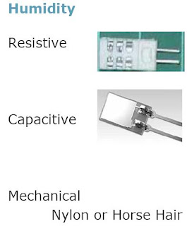
Humidity Energy Savings
No direct energy savings, but….
Achieved by combining with temperature to measure enthalpy
Enthalpy = Total Heat Content controlled to provide ‘Free Cooling’
Te = T + L/cp * w/(1-q) Joules
WhereTe = Heat Content
T = Measured Temperature
L = Latent Heat of vaporisation
Cp = Specific Heat of Dry Air –Constant pressure
q = Humidity
Air Quality –VOC Sensors
VOCs (Volatile Organic Compounds)Made from a metal oxide (SnO2) wrapped around a ceramic heater.When heated, oxygen is absorbed on the surface. Donor electrons are transferred to the absorbed oxygen creating a positive charge in a space charge layer. Surface potential is formed serving as a potential barrier against electron flow. i.e. we have variable resistance proportional to VOCs.This device reacts to a wide variety of gasses, some are desirable for energy saving, others are not.
Air Quality CO2 Sensors
CO2
IR absorption of radiation: non-dispersive infrared (NDIR) technique.
Molecules absorb light (electromagnetic energy) at spectral regions where the radiated wavelength coincides with internal molecular energy levels. By detecting the amount of light absorbed, within a narrow bandwidth that coincides with the resonance wavelength of the species selected, the number of molecules that are free from interference of other species can be measured.
CO2 Energy Saving
Fresh air supply can be adjusted proportional to the CO2 level, which in turn is proportional to the human activity within a space.
In times of low or no occupancy, full re-circulated air can be used saving over 20% of the energy consumption.
Most energy saving is from main plant installations. Individual room control is more for comfort conditions.
EUBAC Certification
Purpose: To apply performance criteria to HVAC devices and ensure that they meet minimum energy and accuracy targets.3rdParty testing of all systems and components, including valves, actuators and sensors.Test houses MUST be independent and be certified to ISO 17021 (Testing Accreditation), and have invested in proper HVAC test equipment.Certificates available on http://www.eubac.org/
Senin, 23 Agustus 2010
4-20mA Current Loop Primer
Introduction
This application note's primary goal is to provide an easy-tounderstand primer for users who are not familiar with 4-20mA current-loops and their applications. Some of the many topics discussed include: why, and where, 4-20mA current loops are used; the functions of the four components found in a typical application; the electrical terminology and basic theory needed to understand current loop operation. Users looking for product-specific information and/or typical wiring diagrams for DATEL's 4-20mA loop- and locallypowered process monitors are referred to DMS Application Note 21, titled "Transmitter Types and Loop Configurations." Despite the fact that the currents (4-20mA) and voltages (+12 to +24V) present in a typical current loop application are relatively low, please keep in mind that all local and national wiring codes, along with any applicable safety regulations, must be observed. Also, this application note is intended to be used as a supplement to all pertinent equipment manufacturers' published data sheets, including the sensor/transducer, the transmitter, the loop power supply, and the display instrumentation.
Why Use a Current Loop?
The 4-20mA current loop shown in Figure 1 is a common method of transmitting sensor information in many industrial process-monitoring applications. A sensor is a device used to measure physical parameters such as temperature, pressure, speed, liquid flow rates, etc. Transmitting sensor information via a current loop is particularly useful when the information has to be sent to a remote location over long distances (1000 feet, or more). The loop's operation is straightforward: a sensor's output voltage is first converted to a proportional current, with 4mA normally representing the sensor's zero-level output, and 20mA representing the sensor's full-scale output. Then, a receiver at the remote end converts the 4-20mA current back into a voltage which in turn can be further processed by a computer or display module.
However, transmitting a sensor's output as a voltage over long distances has several drawbacks. Unless very high input-impedance devices are used, transmitting voltages over long distances produces correspondingly lower voltages at the receiving end due to wiring and interconnect resistances. However, high-impedance instruments can be sensitive to noise pickup since the lengthy signal-carrying wires often run in close proximity to other electricallynoisy system wiring. Shielded wires can be used to minimize noise pickup, but their high cost may be prohibitive when long distances are involved.
Sending a current over long distances produces voltage losses proportional to the wiring's length. However, these voltage losses— also known as "loop drops"—do not reduce the 4-20mA current as long as the transmitter and loop supply can compensate for these drops. The magnitude of the current in the loop is not affected by voltage drops in the system wiring since all of the current (i.e., electrons) originating at the negative (-) terminal of the loop power supply has to return back to its positive (+) terminal—fortunately, electrons cannot easily jump out of wires!
Figure 1. Typical Components Used in a Loop Powered Application
Current Loop Components
A typical 4-20mA current-loop circuit is made up of four individual elements: a sensor/transducer; a voltage-to-current converter (commonly referred to as a transmitter and/or signal conditioner); a loop power supply; and a receiver/monitor. In loop powered applications, all four elements are connected in a closed, seriescircuit, loop configuration (see Figure 1). Sensors provide an output voltage whose value represents the physical parameter being measured. (For example, a thermocouple is a type of sensor which provides a very low-level output voltage that is proportional to its ambient temperature.) The transmitter amplifies and conditions the sensor's output, and then converts this voltage to a proportional 4-20mA dc-current that circulates within the closed series-loop. The receiver/monitor, normally a subsection of a panel meter or data acquisition system, converts the 4-20mA current back into a voltage which can be further processed and/or displayed.
The loop power-supply generally provides all operating power to the transmitter and receiver, and any other loop components that require a well-regulated dc voltage. In loop-powered applications, the power supply's internal elements also furnish a path for closing the series loop. +24V is still the most widely used power supply voltage in
4-20mA process monitoring applications. This is due to the fact that +24V is also used to power many other instruments and electromechanical components commonly found in industrial environments. Lower supply voltages, such as +12V, are also popular since they are used in computer-based systems.
Loop Drops
One of a process monitor's most important specifications—be it a loop-powered or locally powered device—is the total resistance (or "burden") it presents to the transmitter's output driver. Most transmitter's data sheets specify the maximum loop resistance the transmitter can drive while still providing a full-scale 20mA output (the worst-case level with regards to loop burden).
Ohm's Law states that the voltage drop developed across a current-carrying resistor can be found by multiplying the resistor's value by the current passing through it. Stated in mathematical terms:
E = I x R
where E is the voltage drop in volts, I is the current through the resistor in amperes, and R is the resistor's value in Ohms (the 'W' symbol is commonly used to represent Ohms). The sum of the voltage drops around a series loop has to be equal to the supply voltage. For example, when a loop-powered application is powered from a 24V power source, the sum of all the voltage drops around the series loop has to also equal 24V. Every component through which the 4-20mA loop current passes develops a maximum voltage drop equal to that component's resistance
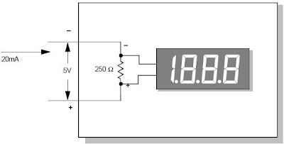
multiplied by 0.020 Amperes (20mA). For example, referring to Figure 2 the DMS-20PC-4/20S's 250W resistance yields a maximum loop drop of :
250W x 0.020A = 5.0V
Loop Drop = 250 W x .020A = 5V
Figure 2. Calculating Loop Drops
Transmitter Ratings
With the above loop-drop theory in mind, and assuming a +24V loop-powered application in which the transmitter's minimum operating voltage is 8V, and the process monitor drops only 4V, a logical question which arises is what happens to the "extra" 12V? The extra 12V has to be dropped entirely by the transmitter since most process monitors have purely resistive inputs combined with zener diodes that limit their maximum voltage drop.
Transmitters usually state both minimum and maximum operating voltages. The minimum voltage is that which is required to ensure proper transmitter operation, while the maximum voltage is determined by its maximum rated power-dissipation, as well as by its semiconductors' breakdown ratings. A transmitter's power dissipation can be determined by multiplying its loop drop by the highest anticipated output current,usually,but not always, 20mA. For example, if a transmitter drops 30V at an overrange output level of 30mA, its power dissipation is:
30V x 0.030A = 0.9 watts
Wiring Resistance
Because copper wires exhibit a dc-resistance directly proportional to their length and gauge (diameter), this application note would not be complete without discussing the important topic of wiring—specifically the effects wiring resistance has on overall system performance.
Applications in which two or more loop-monitoring devices are connected over very long, 2-way wiring distances (1000-2000 feet) normally use +24V supplies because many transmitters require a minimum 8V-supply for proper operation. When this 8-volt minimum is added to the typical 3-4 volts dropped by each process monitor and the 2-4 volts dropped in the system wiring and interconnects, the required minimum supply voltage can easily exceed 16V. The following worked-out example will illustrate these important concepts.
The voltage drop developed along a given length of wire is found by multiplying the wire's total resistance by the current passing through it. The wire's total resistance is found by looking up its resistance (usually expressed in Ohms per 1000 feet) in a wire specifications table. Referring to Figure 3 if a transmitter's output is delivered to a remote process monitor using 2000 feet (660 meters) of 26-guage, solid copper wire having a resistance of 40.8W per 1000 feet, the one-way voltage dropped by the wire when the transmitter's output is 20mA is equal to:
E = 0.020 Amperes x [2000 feet x (40.8W /1000 feet)]
E = 0.020A x 81.6W = 1.63V
However, the current must travel 2000 feet down to the process monitor and another 2000 feet back to the transmitter's "+" output terminal, for a total of 4000 feet. As noted above, 26-gauge wire has a resistance of 40.8W per 1000 feet, yielding a total loop resistance (R) equal to 4000 feet x (40.8W /1000 feet) = 163.2W. The totalvoltage dropped over the 4000 feet of wiring is therefore:
E = 0.020A x 163.2W
E = 3.27V.
Looking down the loop towards the remote process monitor, the transmitter sees the sum of the 3.27V wire drop and the 5.0V process-monitor drop, for a total loop-drop of 8.27V. If the transmitter itself requires a minimum of 8V (this is also considered a voltage drop) for proper operation, the lowest power supply voltage required for the system shown in Figure 3 is 16.3V.
Figure 3. Wiring Resistance Effects
RH Conversion Formulas
To convert transmitter output signal to %RH.
4-20mA to %RH
Example: 12mA transmitter signal output
(12mA-4mA)/ 0.16 = 50% RH
0-5 VDC to %RH
Example: 2 VDC transmitter signal output
2 VDC/0.05 = 40% RH
0-10 VDC to %RH
Example: 8 VDC transmitter signal output
8 VDC/0.10 = 80% RH
SysManSMS Server
High quality mobile notification solution:
Secure internet-free delivery with direct GSM network connection
Easy integration via SysManSMS Server secure mail functions
User management via powerful Number Files and schedules
Text Filters to limit, convert or priorities sending of messages
Full message delivery control with auto re-route if problems
Xenta mobile notification overview
Alarm notification from Xenta-731 and other, can be setup to forward alerts to a mail address.
If the receiving SMTP mail service is a SysManSMS Server, you will be able to forward those alarm to texts mobile phones, using the secure GSM/SMS protocol.
The SysManSMS Server can be located either on the same LAN as the Xenta, or on the Internet.
The Xenta sends alert mails to SysManSMS Server using Number File (Receiver Groups) as address.
By use of group addressing, you may send different alert types to different user groups, and you may also serve many Xenta’s with only one SysManSMS Server.
Security settings on the SysManSMS Server can make sure only selected Xenta’s has access.
The SysManSMS Server’s SMTP service, has support for a lot of advanced functions like User Group Management and deliver schedule schemes - Check for delivery status and re-route if deliver problems – Different message types like the instant “Flash” SMS’s or WakeupCalls.
You may also create a software alarm object in the Xenta to periodical send mail to a SysManSMS Server. This mail can reset a Watchdog alarm, and if a mail is missing (Xenta dead) the SysManSMS Server may send SMS alerts. For more information about such advanced usage – please contact SysMan via www.sysman.no
Configuration components
To configure the Xenta to send its alarms to mobiles, you will need the following components connected via the network:
• Configuration PC with TAC Xbuilder
• TAC Xenta-731 controller
• SysManSMS Server configured with SMTP Service enabled.
Configure SysManSMS Server
On the SysManSMS Server you will need to perform two tasks.
First of all, you must create a Number File to hold mobile numbers for your SMS alert receivers.
Next you must enable the SysManSMS SMTP Service, so that mails from Xenta can be received and converted to mobile SMS messages.
Create a SysManSMS Number File
Create one or more SysManSMS Number Files to hold groups of users to receive Xenta alarms.
Your Number File will match Receiver Group names from Xenta
Start the SysManSMS_NumEdit from Desktop Menu or direct from Utilities folder.
This is the main window of the SysManSMS_NumEdit – Hit the New button
Create an entry for each mobile
This is the EDIT window for creating/editing a number line. Insert a name and mobile number – Hit OK
Save the file into the Iclients folder, with the name XentaAlarms.lst
Enable SysManSMTP Service
By default the SysManSMS Server does not have the SMTP Service enabled.
To enable the service, use the Server Settings and Configure Settings status bar menu entry.From the main configuration window, select MAIL (SMTP) settings.
To change SMTP (Mail) settings,
open SysManSMS desktop menu and select “Server Settings” and “Configure Settings”.
Alternatively run SETUP from CD.
Enable MAIL to SMS Gateway Gateway This will tell SysManSMS Server to start the SMTP Service
Port Number This is the smtp listening port. Default is 25
SMS Length This will specify the maximum length of one mail-sms message
Add Subject Text Subject text from the mail will start the SMS text
Include From address The mail sender’s address will be added to end of SMS text
Allow two SMS per Mail If text greater than maximum, this will allow split into 2 SMS’s
Now hit OK and from the main configuration window, hit CONTINUE to restart SysManSMS Server.
Test SysManSMTP Service
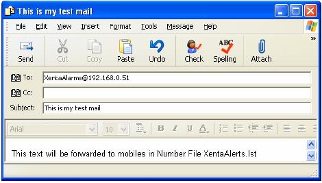
To check out MAIL to SMS functionality, you may send a mail from Microsoft Outlook Express:
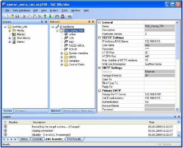
Configure Xenta-731 from TAC Xbuilder
Define your Xenta IP and SMTP settings
Check out alert from Xenta-731
Now connect to the Xenta-731 using a browser
Now check mobiles !
All active numbers in the SysManSMS XentaAlarms.lst Number File should receive the alert.
Langganan:
Komentar (Atom)


